|
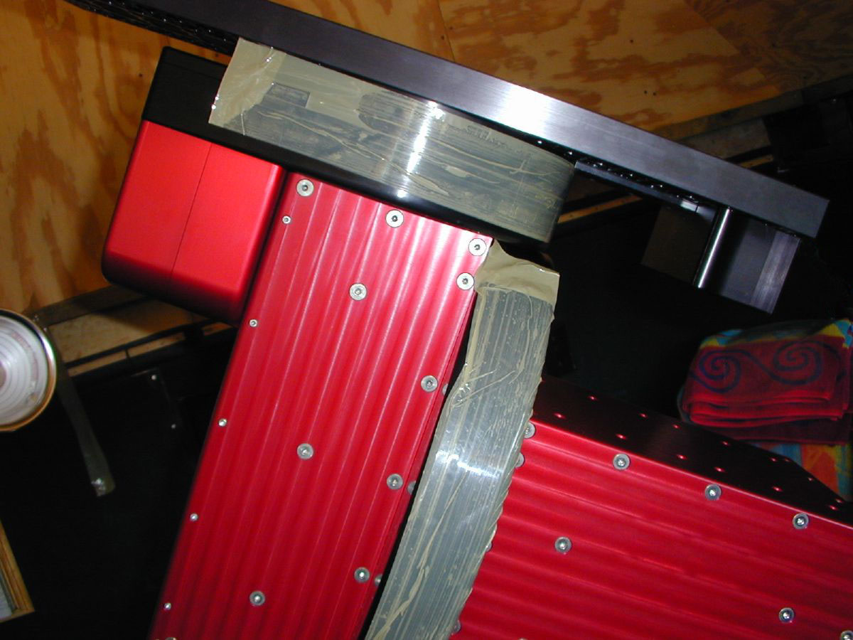
When working on the mount, it is a good idea to put packing tape around the RA and DEC axes and pull the worms back with the adjusters. This keeps the gears from taking on any stress and the tape keeps the axes immobile so the mount is easy to work on.
|
|
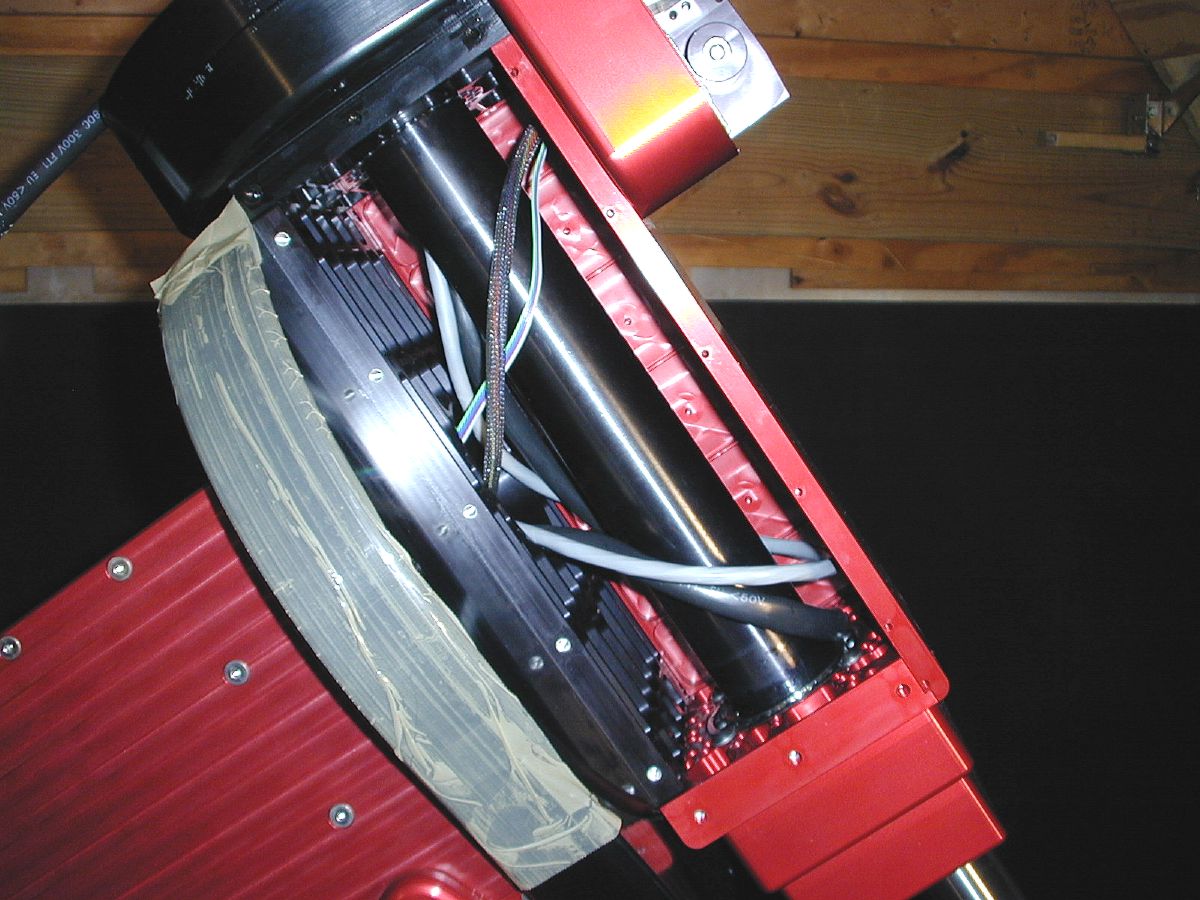
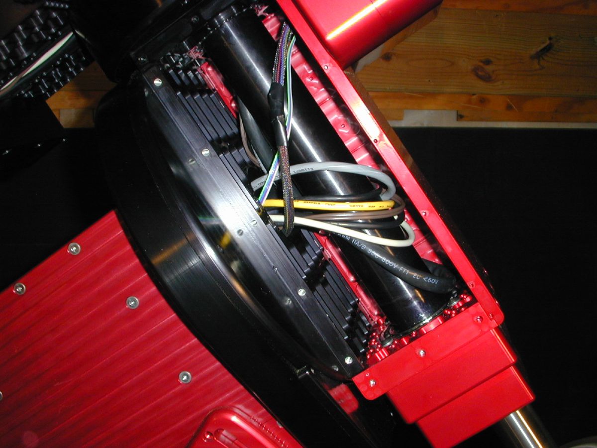
Removing the east side plate exposes the DEC axis and shows the route the new wiring needs to take.
|
|
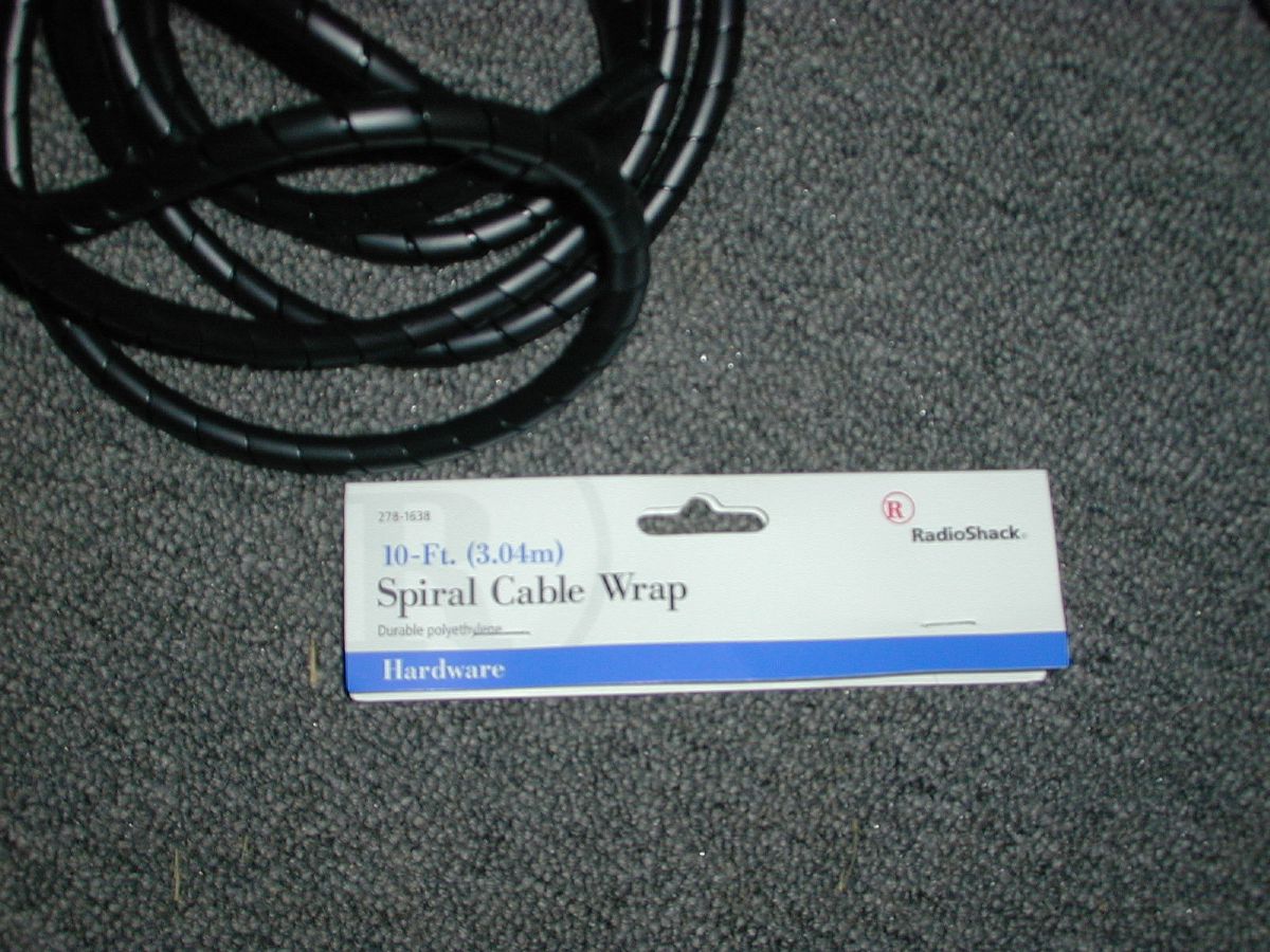
I decided to add 1 - USB, 1 - Cat5, and 1 - 16 gauge 2 conductor cable to take some additional DC power to the top. I also wanted something to help with cable management, and this fit the ticket.
|
|
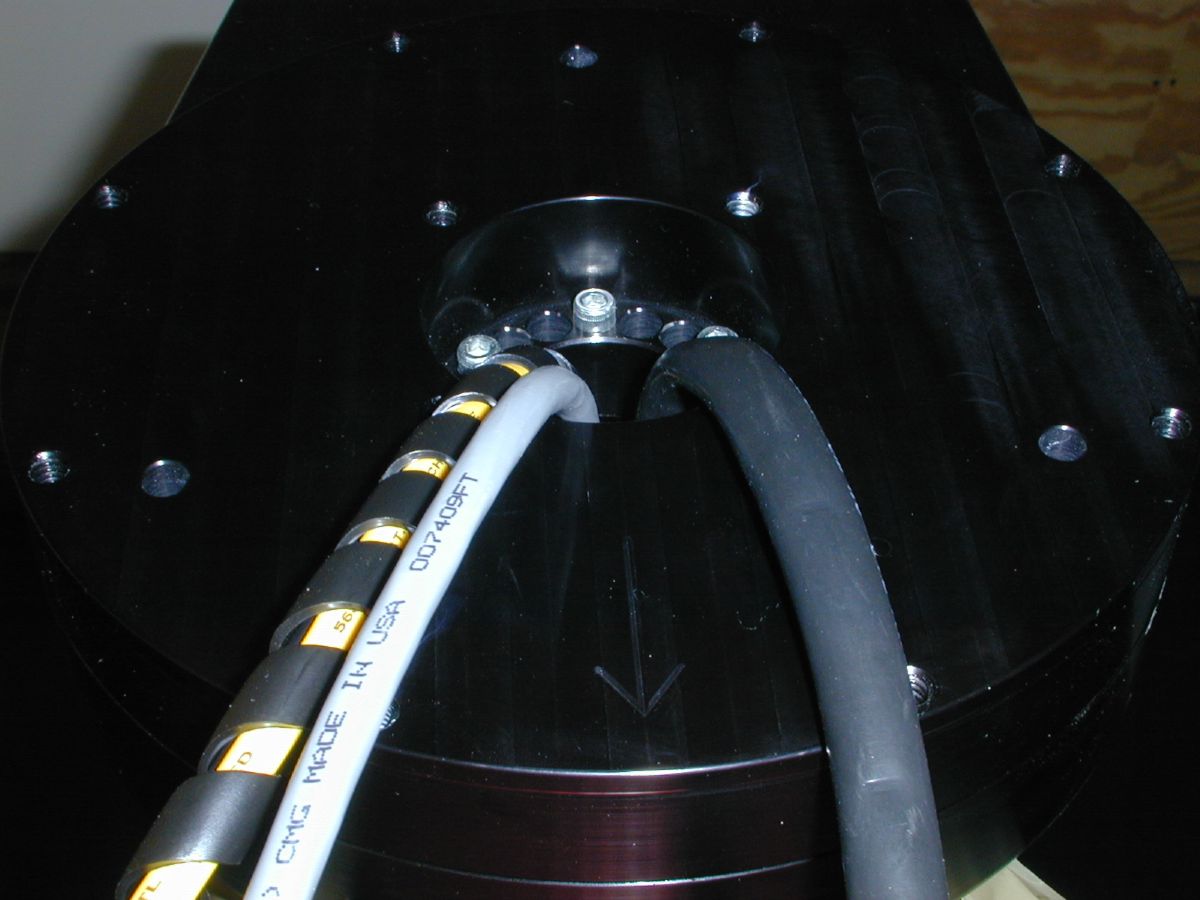
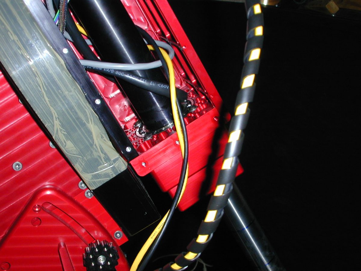
I wrapped the USB and Cat-5 cables together (both being data primarily), and left the 16 gauge cable separate. I started the cables in through the top DEC plate and into the DEC housing.
|
|
I decided not to use the cable wrap inside the DEC housing around the shaft to give the individual wires a little bit more flexibility to minimize any potential for binding as the shaft turns.
|
|
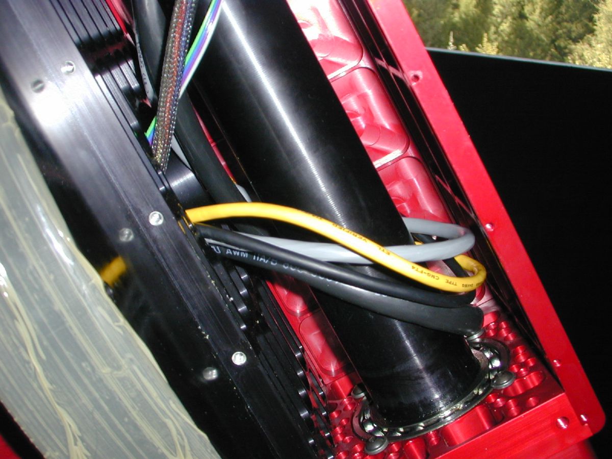
Here you can see the path the wiring follows. The loop around the shaft gives the wiring plenty of slack to allow full movement of the DEC axis without pinching or binding.
|
|
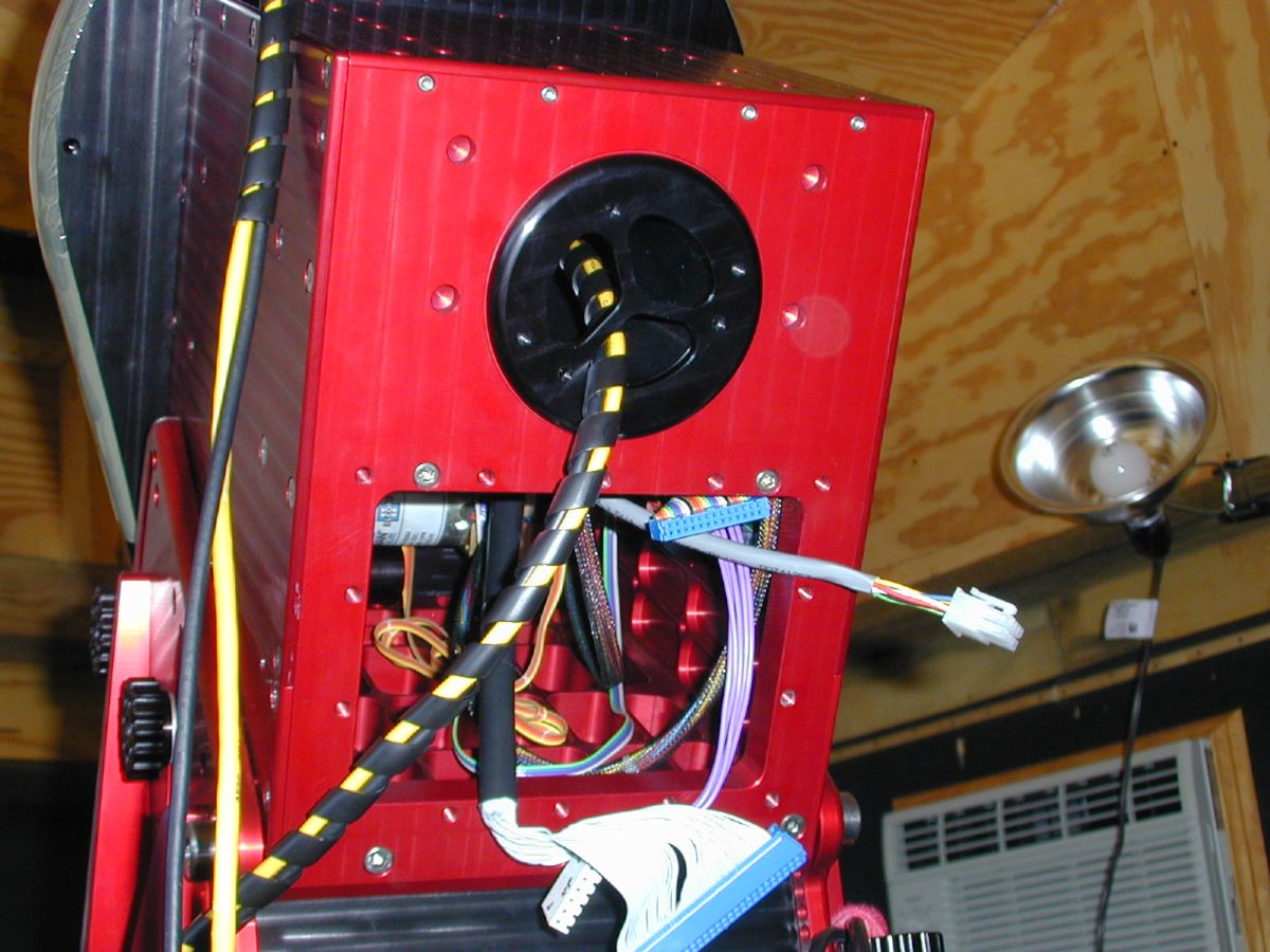
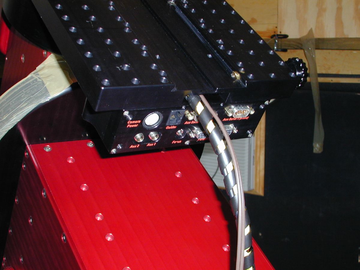
The new cables exit out of the hole above the instrument panel.
|
|
While I had the mount taken apart. I also replaced the original power wiring harness with a new one made with 18 gauge wire. This required me to remove the instrument panel to get to the cable. This was done to ensure that the camera power wasn't being limited by the smaller original harness.
|
|
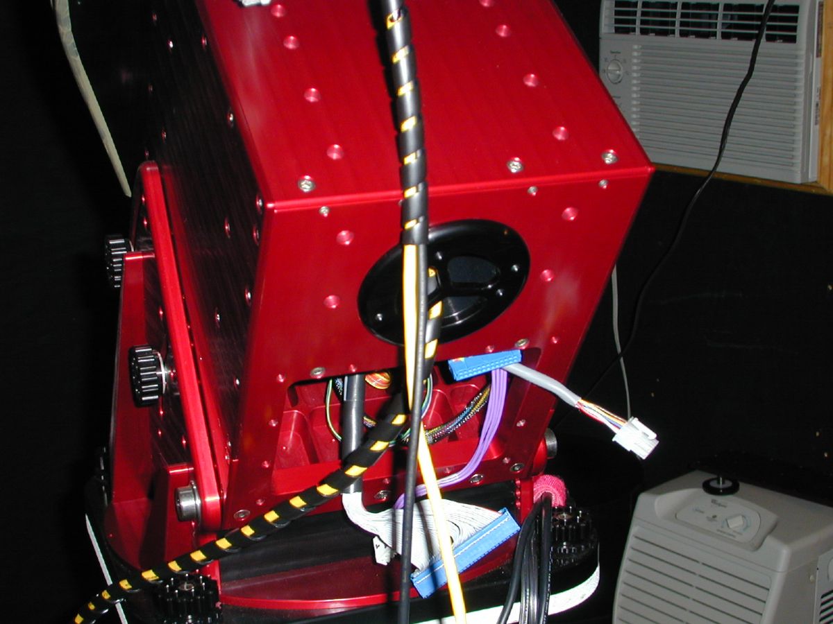
This shows the exit location of the new wiring after the top instrument panel has been reinstalled.
|
|
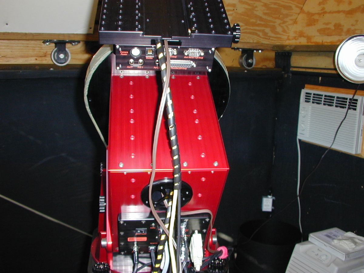
A view from the back with the cables routed through the mount and ready for the scopes to be reinstalled.
|
| ......"UPDATE"...... |
|
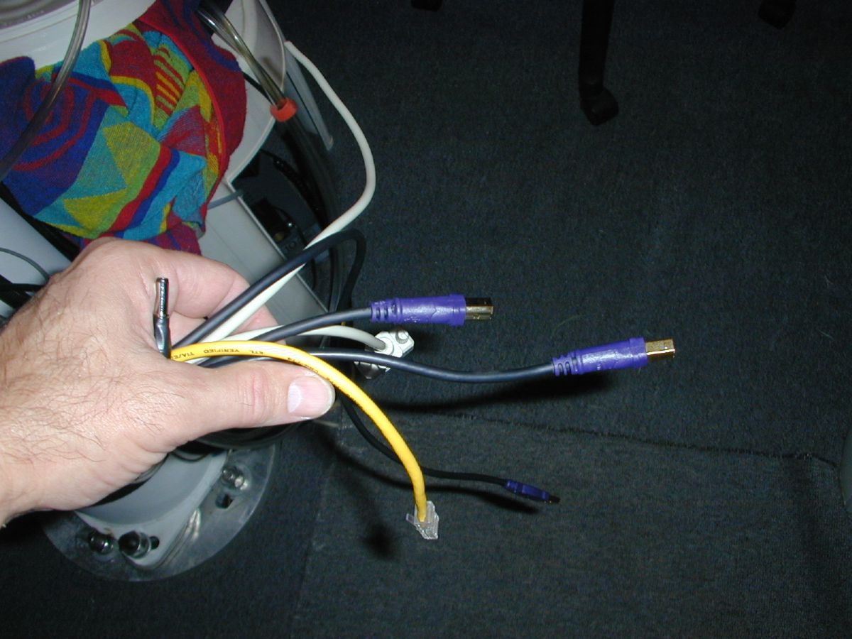
I took my C14 off so I could install a Software Bisque mirror locking collar. I also took this opportunity to install a second USB cable and a full 9 conductor serial cable so I could drive the necessary focusers and cameras. |
|
As you can see, the number of cables required to make everything work keeps increasing.
|
